
Page 31 - Mar17ABS
P. 31
“Not following specified duty cycle procedures will cause the starter to overheat and severely damage the unit’s internal components, leading to premature starter failure,” he said.
Most pilots don’t understand that violating the duty cycle just a couple of times will do irreparable damage to the starter. In extreme cases, it can render the starter inoperable. Excessive cranking can also overheat the electrical supply system and cause accelerated wear to the wiring, contactor and elevated corrosion rates for the connections in the circuit.
The folks at HET feel so strongly about the importance of following proper duty cycle procedures they produced a short training video on the subject. You can see it at: https://www.youtube.com/watch?v=uvnrbUrPy8Y
Starter Due Diligence
As you’ll learn in the informative video, every type of starter has its own particular duty cycle. And it’s critically important for you to know which starter is in your airplane and how its duty cycle works. And so you don’t have to take notes, here are the duty cycles for the most popular starter types as described in Hartzell’s video.
Typical Duty Cycle Times for HET Sky-Tec Starters:
• 10secondsofengagementfollowedby20secondsofrestfor up to six (6) start attempts;
• Afterthat,allow30minutesofcooldownbeforebeginning the next start sequence.
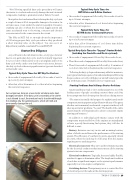
For comparison, here are a new starter armature and a heat- damaged armature. If the duty cycle is exceeded or the starter is not allowed to cool, the armature heat is transferred through the windings into the soldered points, which will melt and permanently damage the unit.
•
•
• •
• • •
Typical Duty Cycle Times for HET E-Drive and X-Drive Starters:
10secondsofengagementfollowedby20secondsofrestfor up to 20 start attempts;
Afterthat,allow10minutesofcooldownbeforebeginning the next start sequence.
Typical Duty Cycle Times for HET PM-Series Continental Starters:
15secondsofengagementfollowedby30secondsofrestfor up to six (6) start attempts;
After that, allow 30 minutes of cool down time before beginning the next start sequence.
Typical Duty Cycle Times for “Legacy” Starter Models (including the Prestolite and Electrosystems):
10 seconds of engagement followed by 60 seconds of rest;
Then10secondsofengagementfollowedby60secondsofrest;
Then 10 seconds of engagement followed by 15 minutes of cool down time before beginning the next start sequence.
“Following the duty cycle procedures may add a few minutes to your typical starting sequence, but understanding and following the procedures correctly will help your aircraft’s starter provide you with many years of reliable service,” Gauntt said.
Starting Problems Aren’t Always Starter Problems
Gauntt said that a weak or slow cranking starter is one of the leading causes of people exceeding a starter’s duty cycle. But, those symptoms don’t always point directly at a dying starter.
“The starter is actually the last part of a sophisticated, multi- component starting system and problems with any of the parts, whether environmental, mechanical or operator-induced, will show up as ‘starter problems,’” he said. “The health of the entire system must be well maintained to achieve consistent engine starting performance.”
In addition to individual performance issues with the components mentioned below, if the engines are misadjusted or have a poorly functioning fuel system, they will also be difficult to start.
Battery: Batteries can vary in size and mounting location, either of which can influence the performance of the starting system. The efficiency of your battery can be especially critical in a twin, where the unit may be well away from the engine, requiring more cranking power.
Electrical connectors: They serve as the termination points for the electrical conductors that interconnect all the starting system’s various components.
Electrical conductors: Typically, these are highly flexible, insulated copper or aluminum cables. The length and condition of each has a significant impact on the system’s performance especially in a twin-engine configuration.
Switching devices: Their primary use is to control the flow of electrical power throughout the starting system.
TWIN & TURBINE • 29
