
Page 28 - TNT Dec 2017
P. 28
Seeing into the Future
Radar reveals only what a storm is. Vertical Profile reveals what it will soon be.
by Archie Trammell
Instantly after radar engineers discovered how to convert millevolts, ohms and dBs into digital code, they begin adding dozens of high-tech features to airborne radars. The digital revolution brought on such things as color displays, turbulence detection, auto tilt, extended STC, REACT,
digitized signal generators, and on and on. None of these technologies add to the two basic things a pilot needs to know to conduct a safe, comfortable flight: “Where is it?” and “What’s a safe path for avoiding its hazards?”
In truth, there have been only two advances in radar engineering of help to pilots in thunderstorm see-and-avoid since that first system designed by George Lucchi of RCA 60 years ago. First was the so-called “flat plate” antenna that came to airborne radars near 50 years ago. Before that, the radiation pattern from our small parabolic antennas was so scattered, half the echoes displayed were false side-lobe returns. The phased array antenna rounded them up into a much cleaner beam.
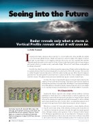
Illustration from the Dr. Kenneth Wilk study of 45 years ago on the growth of various storm types. He found that the echo of a general “Popcorn” storm begins as a weak echo at 20,000 to 30,000 feet. The first red appears at about 22,000 feet, after rain begins to fall.
26 • TWIN & TURBINE
Second of the only two meaningful advances in radar engineering was the addition of Vertical Profile 30 years ago. That was an innovation by engineers at King Radio just after it was acquired by AlliedSignal. A new general manager at the King Division floated the idea by engineering and, since it was simple to do, it quickly became an added feature to the Bendix RDS 81/82 systems.
VP: A Simple Add-On
Creating the feature required only a simple software addition. Antenna stabilization, which has been a common feature of airborne radar since the beginning, requires that the antenna be articulated to swing 30-degree up and down as the antenna sweeps back and forth horizontally to detect weather and terrain ahead from top to bottom. But to accommodate maneuvers of aircraft in both pitch and roll the TILT limits must be about 15 degrees.
Therefore, to create VP it was only necessary to create digital software to stop the side-to-side swing of the antenna at some position and direct it to commence running the antenna vertically through the natural up-and- down, 30-degree limits at that position. Voila! A Vertical Profile feature! A VP 30-degree up-and-down scan. (It was limited to 25 degrees on early systems and 30 degrees on later ones.) Also, later, more software was added to allow pilot selection of which azimuth position VP would scan up and
December 2017
